Project Almond Joy

Wiring
Now it’s time to make some magic happen.
20 Pin Harness

Pretty sure this doesn’t have the joystick wired correctly…
Connect the box connector in the correct orientation to J8 on the Retro board (the empty pins should be on the left). Next, run the bundles to where they’re going to go; use the map of J8 to double check. For buttons, it doesn’t matter what pin you use for positive, but it’s best to use the right side to be consistent. Connect the ground wire daisy chain to the action buttons. Don’t connect the ground wire to the option buttons yet.
Since this is a Korean switch, attach the converter cable to the joystick lead, then attach the leads to the correct switches. Grounds go on the top of the switch and positives go to the other tab. The colors that worked here were:
| Joystick Direction | Wire Color | Switch Direction |
|---|---|---|
| Up | Orange | Left |
| Down | Red | Right |
| Left | Yellow | Up |
| Right | Green | Down |
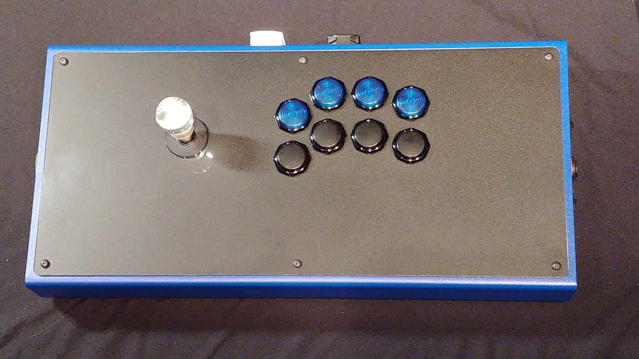
In this table, “Joystick direction” is what direction the joystick moves in. “Wire color” is what it says on the tin (may vary depending on your harness). “Switch direction” is what direction the tabs point when you’re looking at it from overhead and the top option buttons facing away, like in the above picture.
L3/R3/TP
Connect the L3/R3/TP connector to J10 on the Retro board (make sure to orient it correctly), then connect the positive leads to their respective buttons (I used the right bank of buttons behind the joystick).
RJ45
Connect the short RJ45 cable between the interior Neutrik RJ45 and the RJ45 port on the Retro board.
DP/RS/LS
Connect the DP/RS/LS cable to J3 on the Retro board, then connect their respective pins to the DPST (on-off-on) switch. Make sure the terminals are covered.
UFB/Retro Switch
Connect the UFB/Retro lead between J2 on the Retro and to their respective pins on the SPST switch for this. Red to pin 1, green to pin 2, black to pin 3. Keep in mind the pins may be reversed.
LED Status Array
(Coming soon!)
Turbo Key & LED
Connect the turbo lead to J6 on the Retro board. Connect the red/white lead to the turbo LED, and the blue/black lead to the turbo button.
Tournament Lockout
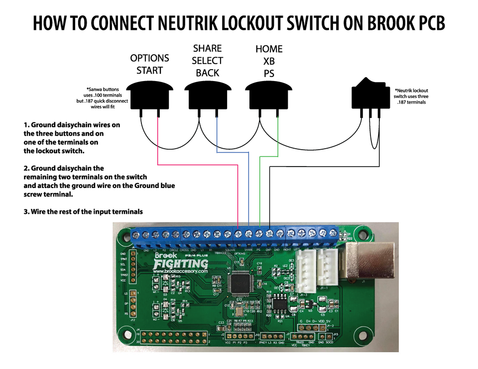
Connect the converter harness to the TL switch (red on pin 1, white on pin 2, black on pin 3). Connect two leads of the ground coming from the start/select/guide to pin 2 & 3, then use the TL harness to connect from pin one to the ground on the start, select, and guide buttons.
