Project Almond Joy
Build Process

The first step was to unwrap the AFS case, and remove the plexi covering. A few tips for this:
- Save some of the bubble wrap to lay down as a protective layer on your work surface.
- If you have some rubber gloves, those can prevent fingerprints from getting on the plexiglass. This makes it a challege to get the wrap off the plexi though…
- You can use the mini-screwdriver with hex 2.0 and hex 2.5 heads to remove the panels, or Torx 8 and 10.
- The back panel’s plexi is held in by nuts, so hold on to those while you unscrew them.


After the plexi wrap is removed, clean it off (glasses cleaner spray works well enough), then reattach it. If you have an art insert, this is the time to add it.
Neutrik Port Install

I actually installed the action buttons before this step, but recommend doing this first. Start by removing the existing screws and nuts, then prep the Neutrik port, screws, and gasket. Put the tiny (and highly loseable) brass rings into the gasket holes (these are meant to protect the gasket from being torn by the mounting screws). Remove the front plate from the Neutrik RJ45 and put it into the gasket. Slide the port into position, minding the push tab, and then put the gasket (and cover if you have it) on, then the face plate. Screw them on firmly, but not too tightly. If you want to use a SCDX cover, put that on top of the face plate before screwing it in.
For this build, I had some blank covers 3D-printed and installed. Those only need the included screws and nuts to hold them in. You can find the model files here.
Other tips here:
- One of the brass rings is going to fall out and require a 10 minute search. Magnets won’t work on them either. Just accept it. (Thanks to Keeson at AFS for enlightening me what they’re even for)
- SCDX covers are available in white, black, blue, and green. The SCDP gasket is available in red, yellow, blue, green, white, and black.
- Don’t want to buy a gasket and have access to 3D printing? Use this. If you have access to multiple colors, you can color code your connections (e.g. blue for UFB, orange for Retro…)
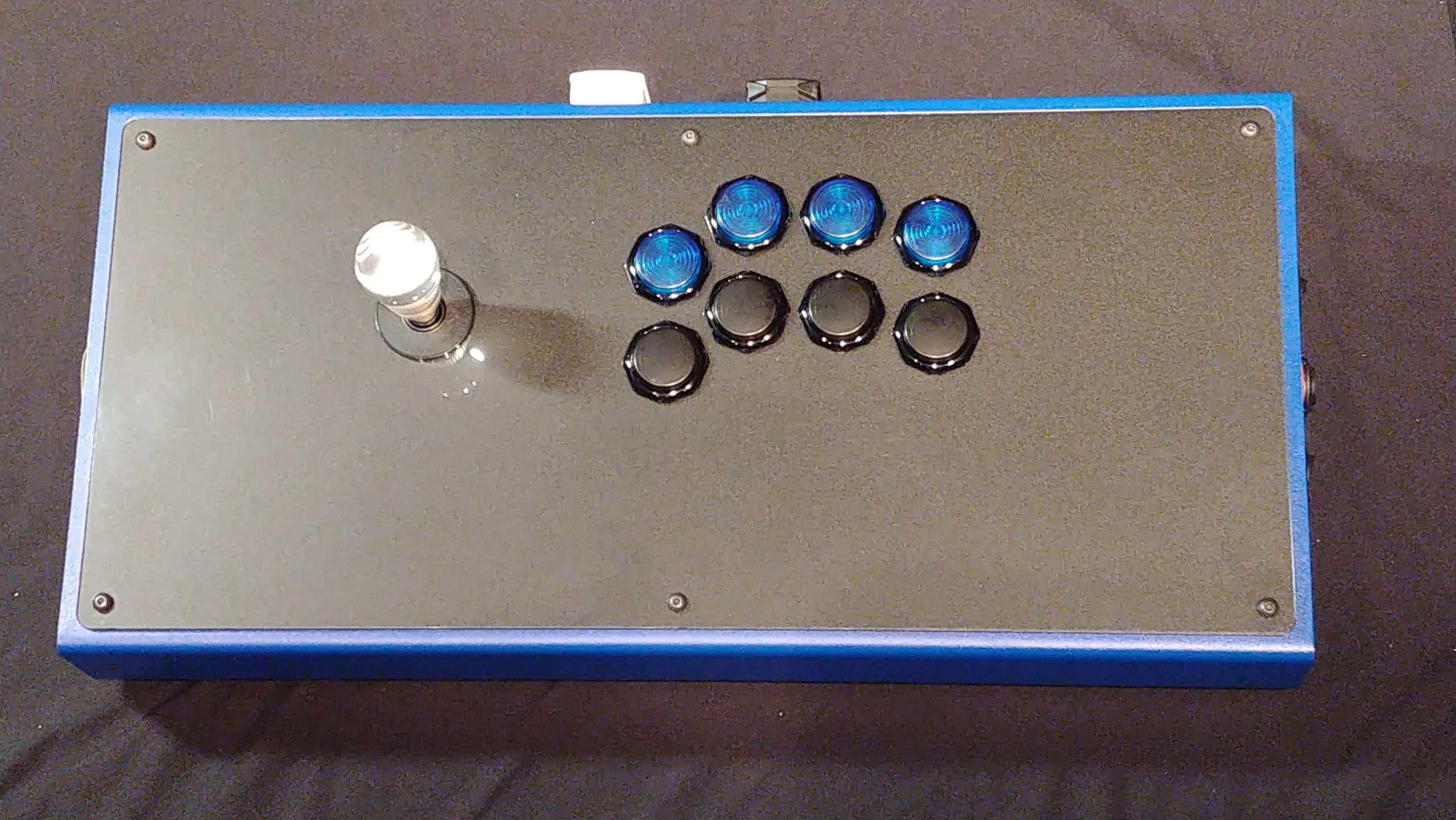
Button Install

Previous IL buttons 
Previous IL buttons 
GamerFingers installed 
Samducksa option buttons 
Samducksa option button, button hole covers
[Focus Attack GamerFinger button how to video]
Ultimately this ended up with the GamerFinger HBFS-30mm for action buttons and the Samducksa 24mms, but originally I was going to use Industrias Lorenzo buttons for their old-school feel. Unfortunately, even the short stem PSLs bump against either the metal or plexi parts of the bottom, and that poses some serious issues. I migrated these over to an XArcade we picked up, replacing the stock buttons.
Buttons are trivial to install; for the Samducksas, just remove the lock nut slide them into position (using the option button holes), line them up, then lock them in with the lock nut. For the 30mm GFs, I didn’t order switches as I wanted to use my own from Novelkeys – the Greetech greens work well to provide the higher tension and clicky sound that my husband likes.
I went with screw in-type buttons here, but could’ve used snap in; the former take a little more time to install but are easier to uninstall if needed.
For the GFs, start by removing the lock nut. With the plunger cap off, locate the small pinholes for the Cherry switch, and line up your switch with them. Push down firmly once they align; you should feel it sit. Next, put the desired plunger cap on, aligning the cut out tabs with the cut outs on the barrel as well as the plus shape of the cap to the plus shape of the key switch. Press down firmly to attach. Leave the protective film on until you’re ready for final testing.
Slide the barrel into the desired button slot, line up the connector tabs the way you want them, and then use the lock nut to secure the button.
Some Tips:
- Novelkeys is your friend for key switches.
- Line up the buttons using the logo and prong orientation while not having the button screwed in fully. Consider how you’ll run wire to them.
- Make sure the key switches are firmly seated. I’ve had buttons fail just for not doing this.
- The Samducksas retained their Cherry MX Speed Silvers (they’re just too much of a pain to open up to me, especially compared to the GFs).
- IL and Happ buttons (traditional American) will fit the 30mm hole, but are a little too long with their switches attached (long stem will not fit at all, short will barely fit and you need to make sure the switches are covered). They are NOT recommended.
- For screw in buttons, make sure the surface that comes in contact with the case has the grippy teeth on them.
- If using key switch based buttons and the switches you have are PCB mount (have extra plastic pins), you can use toenail clippers to clip these to convert them to plate mount. You may want to file down those spots to be sure.
PCB Mounting

I don’t recommend this arrangement. 
That’s better.
The PCB is the brains of your controller, relaying signals to your console. I went with the Brook Retro because it works with many of the old school systems; most importantly the Saturn, Dreamcast, and Playstation 2. Later I’ll likely add a Ultimate Fighting Board (UFB) to it.
Mounting the board is easy; just remove the four small screws on the acrylic mounting board, put the board on (preferably with the RJ45 port pointed toward the joystick end), then put the screws back in. Easy. One quick tip for this: Have a cup, bowl, tray, or what not to hold screws and such so they don’t get loose. Connect the RJ45 to the Neutrik passthrough.
Joystick Mounting

As seen in the last gallery, the Crown lever is mounted by taking off the four lock nuts on the joystick posts, then sliding the joystick in. Thankfully, because the stick is removable, you can keep the case on its front as you continue to work on it; otherwise, I’d save this for last.
Because this is a Korean lever that uses individual switches, it doesn’t matter which direction you mount it. Unfortunately, there’s no included documentation on what switch belongs to what. Right now though, we’re just concerned with putting pieces on.
You will want a nut driver to secure the locking nuts once the base is mounted, but otherwise, this is easy work.
Switch Mounting

To take advantage of the features in the Brook Retro board, I wanted to have a bank of switches on one side that would function as the following:
- A tournament lockout that would disable Start/Select/Guide
- A Directional Pad/Left Stick/Right Stick toggle
- A toggle for future Retro/UFB switching
Because the option buttons are 24mm and most switches are 20mm, I searched for 24mm switches and only found that the on-off (SPST) type come in that size from a company named SCI. These can be found in packs of four on eBay in both red and green LED variants (though the LEDs aren’t going to work here). Sourcing a 24mm on-off-on (DPST) switch was impossible, so I ordered a generic one and used the housing from a Sanwa 24mm button.
Mounting the switches is fairly straight forward. For the SCI switches, you need to cut a (very) small notch to accommodate the locking tab; I used a metal file on a Swiss army knife, but you can use a Dremel with a cutting wheel. I faced one switch with the LED to the front, and the other to the back. Take your time with this, and test often.
For the middle switch, use the mini-screwdriver to press on the plunger tabs located on the barrel and remove that, then push in on the tabs on the switch on the bottom. Nudge that assembly through the barrel and set both that plunger and switch aside. You’ll now need to Dremel out the bottom as well as a little on the sides.
Load a small grinding bit and set the speed to your lowest setting (plastic will easily melt and grind). Carefully use the tool to open out the bottom of the barrel from the square shape out into a wider circle. This will make the pins on the bottom of the switch accessible.
Next, grind a little of the inner lip of the barrel to allow the retaining tabs of the three way switch to slot in (you can use the retaining slots as guides for where to create a little space). As with the slot cutting, go slow and test often. Once you have enough, you can get the switch into the barrel. Next, just put the switch into the side panel, and put the locking nut on.